| Cell Name | Description |
|---|
| Code_Generator |
Super-cell that contains the entire project-in-frame |
| project |
The unframed project |
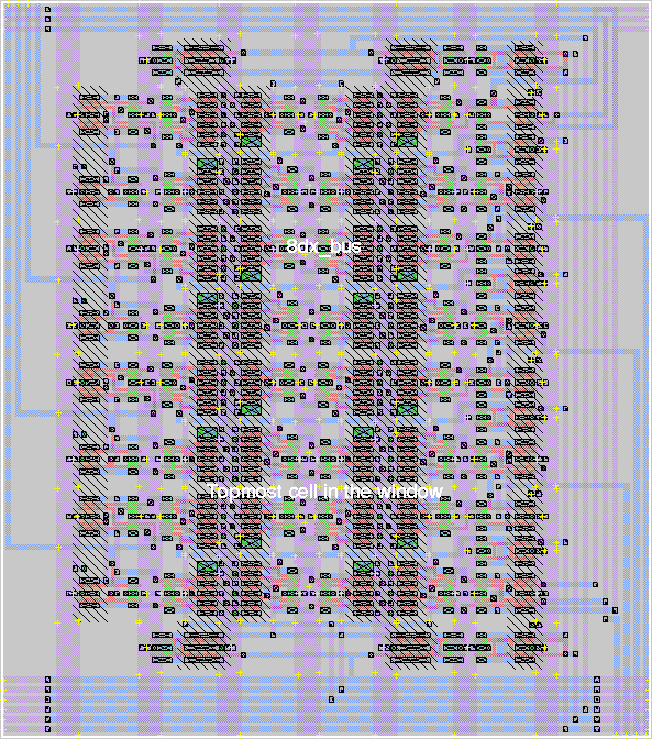
| 24dx |
Contains 3 8dx_bus cells. Main body of PRN |
| 8dx_bus |
8 DX stages, with bussing lines attached. (built from 8dx_cd) |
| 8dx_cd |
8 DX stages, with clock drivers (build from 8dx) |
| 8dx |
8 DX stages (built from 2 4dx cells) |
| 4dx |
4 DX stages (built from 2 2dx cells) |
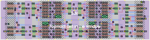
| 2dx |
2 DX stages. The DX stage is the basic stage of the circuit,
consisting of a D Flip-Flop followed by an XOR gate. |
| 2msff |
Two Master-Slave flip-flops, the basis for the D flip-flop.
(build from msff) |
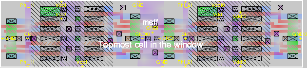
| msff |
A single Master-Slave flip-flop. This has a D, /D, Clk, /Clk and Set
input. It provides a Q and /Q output. |
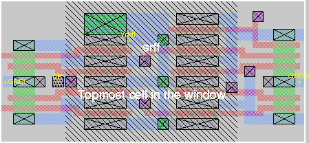
| srff |
A single Set-Reset flip-flop. This has a clocked Set and Reset input,
as well as a non-clocked Set input. The S and R inputs correspond to
D and /D. |
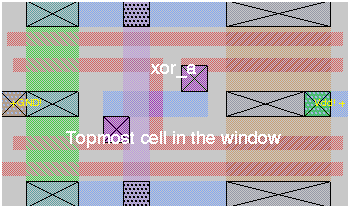
| xor_a |
This is the body of an XOR gate. It accepts A, /A, B, and /B, and gives
A xor B. |
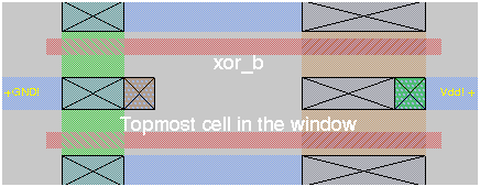
| xor_b |
This is actually a pair of inverters, used for either generating the
/A and /B for the XOR input, or for inverting the XOR output if one of
the inputs is already available inverted. |
| inv |
Generic inverter. |
| drv_2 |
Double-sized inverter/driver. |
| drv_4 |
Quadruple-sized inverter/driver. |
| drv_6 |
Sextuple-sized inverter/driver. |
| ee563 |
The text string "EE 563" |
| names |
The text string "Joe Zbiciak" and "Chris Witte" |
| text |
The text string "The generation of random numbers is too important
to be left to chance" |
| copyr |
Textual copyright notice. |
| 40pc22x22_stuffed |
The pad frame. The cells below are contained in the pad frame and
were not designed by myself. |
| gnd | N/A |
| io | N/A |
| vdd | N/A |
| cg | N/A |
| cg_r | N/A |
| cv | N/A |
| cv_r | N/A |