The SP-0256 Speech Processor is an extension to the General Instruments SP-0250 speech processor. The SP-0250 Speech Processor is a 12-pole IIR filter / LPC-based speech generator. It is constructed from a single two-pole filter stage and some control circuitry that multiplexes filter coefficients and samples to achieve a 12-pole filter. It provides a pitch and noise generator for exciting the filter, thus providing all of the necessary equipment for LPC-based speech synthesis.
The original SP-0250 was suitable for generating synthetic voice, but it requires significant attention from the host microprocessor as it consumed speech data. Also, the speech data itself tended to occupy quite a bit of space. The SP-0256 addresses these issues by adding a small microsequencer to the device which is responsible for updating speech core's LPC coefficients. It additionally provides a rudimentary but effective form of compression, as words and phrases could be constructed from small subroutines, and individual filter updates could be restricted to a subset of the total parameter set, encoding only the significant bits.
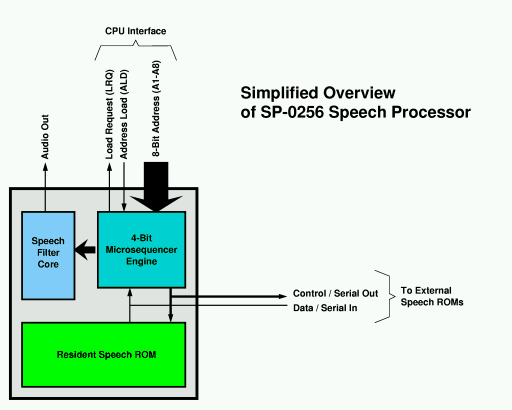
The SP-0256 consists of the following elements:
This diagram gives a rough overview of the SP-0256's architecture:
The digital filter contains all of the pieces necessary to generate the actual speech sounds. The impulse generator and IIR filter model the vocal tract by shaping the periodic impulses in a similar manner to how the human vocal tract shapes sound. This core operates largely independently of the microsequencer, except that it relies on the microsequencer to receive parameter updates, and it notifies the microsequencer when it completes an utterance.
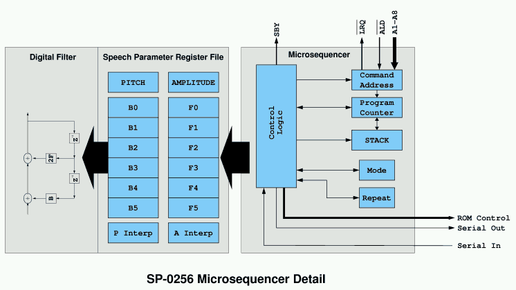
The microsequencer is a simple machine which focuses soley on copying parameters from its input to the filter parameter registers in the filter core. It can zero, replace or delta-update the existing values of the filter registers. It is also capable of branching and jumping to subroutines. The sequencer is not Turing complete, in that it is not capable of conditional flow.
In order to control the filter core, the microsequencer can address 17 different registers in the filter core. Those registers are:
| Register | Size | Purpose |
|---|---|---|
| Repeat | 6 bits | Repeat counter |
| Pitch | 8 bits | Pitch period. A period of 0 generates white noise for unvoiced sounds. |
| Amplitude | 8 bits | Speech amplitude, in floating-point format. It is divided into two fields -- the 3 MSBs provide the exponent and the 5 LSBs provide the mantissa. |
| B0 | 8 bits | Filter coefficients |
| F0 | 8 bits | |
| B1 | 8 bits | |
| F1 | 8 bits | |
| B2 | 8 bits | |
| F2 | 8 bits | |
| B3 | 8 bits | |
| F3 | 8 bits | |
| B4 | 8 bits | |
| F4 | 8 bits | |
| B5 | 8 bits | |
| F5 | 8 bits | |
| Pitch Interpolation | 8 bits | Delta update value applied to pitch after each period. |
| Amplitude Interpolation | 8 bits | Delta update value applied to amplitude after each period. |
Additionally, the microsequencer has a couple registers of its own. These registers primarily control how the microsequencer behaves.
| Register | Size | Purpose |
|---|---|---|
| MODE | 2 bits | Controls the format of data which follows various instructions. In some cases, it also controls whether certain filter coefficients are zeroed or left unmodified. The exact meaning of MODE varies by instruction. MODE is sticky, meaning that once it is set, it retains its value until it is explicitly changed by Opcode 1000 (SETMODE) or the sequencer halts. |
| REPEAT PREFIX | 2 bits | The parameter load instructions can provide a four bit repeat value to the filter core. This register optionally extends that four bit value by providing two more significant bits in the 2 MSBs. By setting the repeat prefix with Opcode 1000 (SETMODE), the program can specify repeat values up to $3F (63). This register is not sticky. |
| PAGE | 4 bits | The PAGE register acts as a prefix, providing the upper four address bits for every JMP and JSR instruction. The PAGE register can hold any binary value from 0001 to 1111, and is set by the SETPAGE instruction. It is not possible to load it with 0000. It powers up to the value 0001, and it retains its value across JMP/JSR instructions as well as sequencer halts. |
| PC | 16 bits | This is the program counter. This counter tracks the address of the byte that is currently being processed. A copy of the program counter is kept in every Speech ROM that is attached to the SP0256, so that the program counter is only broadcast on JMP or JSR. |
| STACK | 16 bits | This is where the program counter is saved when performing a JSR. The STACK has room for exactly one address, so nested subroutines are not possible. It holds the address of the byte following the JSR instruction. |
| COMMAND | 8 bits | This holds address of the most recent command from the host CPU. Addresses are loaded into this register via external pins and the ALD control line. When the microsequencer is halted (or is about to halt), it watches for an address in this register. When a new command address is available, it copies these bits to bits 1 through 8 of the program counter. Bits 0, 9 through 11, and 13 through 15 are forced to zero. Bit 12 is forced to 1 so that code executes out of page $1. |
This diagram gives a conceptual overview of how the microsequencer interfaces to the rest of the machine.
The microsequencer's instruction set can be divided into three primary categories:
Speech parameter updates are generally followed by a data block whose format depends on the particular instruction issued. Most of these instructions only update a subset of the total speech parameter set, and often they update only the most significant bits of the registers they modify. The data blocks themselves are a variable number of bits, and are not constrained to byte boundaries.
The instruction stream itself is processed as a sequence of bits, not bytes, and so instructions and their data blocks can start on any bit boundary. Ordinarily, there are no gaps between instructions, and so the machine largely behaves as a bit-aligned machine. Control transfer instructions introduce alignment points, as all addresses in the system are byte addresses, and so all branch targets (including the return-branch target for RTS) are on byte boundaries. It is customary to pad the data stream with 0s at alignment points (eg. after JSR instructions).
The instruction reference below shows the exact data formats that each instruction requires. Note that the data format for an instruction varies according to the current MODE setting, and so the machine provides a large variety of data formats.
Other important things to note are:
On instructions that accept a repeat count, a repeat count of zero causes the instruction to not execute, which means that no data block follows the instruction in that case. (My disassembler currently does not handle this case.) (This part may be in error. Conflicting documentation suggests there's more going on here than we worked out.)
As a matter of convention in this document, bits are packed into bytes left-to-right, with the leftmost bit going in the MSB of the first byte, and the LSB of the first byte being logically adjacent to the MSB of the second byte. This is likely backwards from how the hardware looks at it, but it is the most natural for a human interpreting the data, as it reads from left-to-right.
Most bit fields, except those which specify branch targets, are bit reversed, meaning the left-most bit is the LSB.
Bit fields narrower than 8 bits are MSB justified unless specified otherwise, meaning that the least significant bits are the ones that are missing. These LSBs are filled with zeros.
When updating filter coefficients with a delta-update, the microsequencer performs plain 2s-complement arithmetic on the 8-bit value in the coefficient register file. No attention is paid to the format of the register.
| Key for opcode formats below | |
|---|---|
| Field | Description |
| Amplitude bits. The 3 rightmost bits are the exponent. The exponent determines what power of 2 is applied to the lower 5 bits. | |
| Pitch period. When set to 0, the impulse switches to random noise. For timing purposes, noise and silence have an effective period equivalent to period==64. | |
| B coefficient data. The 'S' is the sign bit, if present. If there is no 'S' on a given field, the sign is assumed to be 0. | |
| F coefficient data. | |
| Repeat bits. On Opcode 1000 (SETMODE), the repeat bits go to the two MSBs of the repeat count for the next instruction. On all other instructions, the repeat bits go to the four LSBs of the repeat count for the current instruction. | |
| Mode bits. These are set by Opcode 1000 (SETMODE), and they control the data format for a number of other instructions. | |
| Byte address for a branch target. Branch targets are 16 bits long. The JMP/JSR instruction provides the lower 12 bits, and the PAGE register provides the upper 4 bits. The PAGE register is modified via the SETPAGE instruction, Opcode 0000. | |
| Amplitude delta. (unsigned) | |
| Pitch delta. (unsigned) | |
| Amplitude delta. (2s complement) | |
| Pitch delta. (2s complement) | |
| Filter coefficient deltas. (2s complement) | |
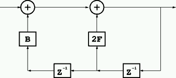
For reference, each 2nd order filter section looks like so. Note that "1/Z" represents a single unit delay. Altogether, there are 6 such stages, yielding a 12 pole filter. The exact ordering of the stages with respect to the coefficient data formats appears to be straightforward, with the lowest-numbered coefficient pair used in the earliest filter stage, etc.
| Opcode | Mnemonic | Description |
|---|---|---|
| 0 0 0 0 | RTS/SETPAGE | Return OR set the PAGE register |
| 0 0 0 1 | LOADALL | Load All Parameters |
| 0 0 1 0 | LOAD_2 | Load Pitch, Amplitude, Coefficient, and Interpolation Regsisters |
| 0 0 1 1 | SETMSB_3 | Load Pitch, Amplitude, MSBs of 3 Coefficients, and Interpolation Registers |
| 0 1 0 0 | LOAD_4 | Load Pitch, Amplitude, Coefficients (2 or 3 stages) |
| 0 1 0 1 | SETMSB_5 | Load Pitch, Amplitude, and MSBs of 3 Coefficients |
| 0 1 1 0 | SETMSB_6 | Load Amplitude and MSBs of 2 or 3 Coefficients |
| 0 1 1 1 | JMP | Jump to 12-bit PAGE-relative Address |
| 1 0 0 0 | SETMODE | Set the Mode bits and Repeat MSBs |
| 1 0 0 1 | DELTA_9 | Delta update Amplitude, Pitch and 5 or 6 Coefficients |
| 1 0 1 0 | SETMSB_A | Load Amplitude and MSBs of 3 Coefficients |
| 1 0 1 1 | JSR | Jump to Subroutine (12-bit PAGE-Relative Address) |
| 1 1 0 0 | LOAD_C | Load Pitch, Amplitude, Coefficients (5 or 6 stages) |
| 1 1 0 1 | DELTA_D | Delta update Amplitude, Pitch and 2 or 3 Coefficients |
| 1 1 1 0 | LOAD_E | Load Pitch, Amplitude |
| 1 1 1 1 | PAUSE | Silent pause |
| OPCODE 0000 | RTS / SETPAGE | Return or set the PAGE register |
|---|---|---|
| Format | LLLL 0000 | |
| Action |
It slices, it dices, it juliennes! It's a floor wax! It's a dessert topping! It's two instructions in one!
|
|
| OPCODE 0001 | LOADALL | Load All Parameters |
|---|---|---|
| Format | RRRR 0001 [data] | |
| Data Formats, by MODE |
MODE x0 |
AAAAAAAA PPPPPPPP BBBBBBBS FFFFFFFS (coeff pair 0) BBBBBBBS FFFFFFFS (coeff pair 1) BBBBBBBS FFFFFFFS (coeff pair 2) BBBBBBBS FFFFFFFS (coeff pair 3) BBBBBBBS FFFFFFFS (coeff pair 4) BBBBBBBS FFFFFFFS (coeff pair 5) |
| MODE x1 |
AAAAAAAA PPPPPPPP BBBBBBBS FFFFFFFS (coeff pair 0) BBBBBBBS FFFFFFFS (coeff pair 1) BBBBBBBS FFFFFFFS (coeff pair 2) BBBBBBBS FFFFFFFS (coeff pair 3) BBBBBBBS FFFFFFFS (coeff pair 4) BBBBBBBS FFFFFFFS (coeff pair 5) aaaaaaas ppppppps (pitch and amplitude interpolation) |
|
| Action | Loads amplitude, pitch, and all coefficient pairs at full 8-bit precision. | |
| Notes |
|
|
| OPCODE 0010 | LOAD_2 | Load Pitch, Amplitude, Coefficients, and Interpolation registers. |
|---|---|---|
| Format | RRRR 0010 [data] | |
| Data Formats, by MODE |
MODE 00 |
AAAAAA PPPPPPPP BBB FFFFS (coeff pair 0) BBB FFFFS (coeff pair 1) BBB FFFFS (coeff pair 2) BBBB FFFFFS (coeff pair 3) BBBBBBS FFFFFS (coeff pair 4) aaaaa ppppp (Interpolation register LSBs) |
| MODE 01 |
AAAAAA PPPPPPPP BBB FFFFS (coeff pair 0) BBB FFFFS (coeff pair 1) BBB FFFFS (coeff pair 2) BBBB FFFFFS (coeff pair 3) BBBBBBS FFFFFS (coeff pair 4) BBBBBBBS FFFFFFFS (coeff pair 5) aaaaa ppppp (Interpolation register LSBs) |
|
| MODE 10 |
AAAAAA PPPPPPPP BBBBBB FFFFFS (coeff pair 0) BBBBBB FFFFFS (coeff pair 1) BBBBBB FFFFFS (coeff pair 2) BBBBBB FFFFFFS (coeff pair 3) BBBBBBBS FFFFFFFS (coeff pair 4) aaaaa ppppp (Interpolation register LSBs) |
|
| MODE 11 |
AAAAAA PPPPPPPP BBBBBB FFFFFS (coeff pair 0) BBBBBB FFFFFS (coeff pair 1) BBBBBB FFFFFS (coeff pair 2) BBBBBB FFFFFFS (coeff pair 3) BBBBBBBS FFFFFFFS (coeff pair 4) BBBBBBBS FFFFFFFS (coeff pair 5) aaaaa ppppp (Interpolation register LSBs) |
|
| Action | Loads new amplitude and pitch parameters. Also loads a set of new filter coefficients, setting the unspecified coefficients to zero. The exact combination and precision of filter coefficients that are loaded is determined by which prefix is used. Opcode 1000 (SETMODE) provides the prefix bits. | |
| Notes |
|
|
| OPCODE 0011 | SETMSB_3 | Load Pitch, Amplitude, MSBs of 3 Coefficients, and Interpolation Registers. |
|---|---|---|
| Format | RRRR 0011 [data] | |
| Data Formats, by MODE |
MODE 0x |
AAAAAA FFFFS (New F0 MSBs) FFFFS (New F1 MSBs) FFFFS (New F2 MSBs) aaaaa ppppp (Interpolation register LSBs) |
| MODE 1x |
AAAAAA FFFFFS (New F0 MSBs) FFFFFS (New F1 MSBs) FFFFFS (New F2 MSBs) aaaaa ppppp (Interpolation register LSBs) |
|
| Action | Loads new amplitude. Also updates the MSBs of a set of new filter coefficients. The Mode prefix bits controls the update process as noted below. Opcode 1000 (SETMODE) provides the prefix bits. | |
| Notes |
|
|
| OPCODE 0100 | LOAD_4 | Load Pitch, Amplitude, Coefficients (2 or 3 stages) |
|---|---|---|
| Format | RRRR 0100 [data] | |
| Data Formats, by MODE |
MODE 00 |
AAAAAA PPPPPPPP BBBB FFFFFS (coeff pair 3) BBBBBBS FFFFFS (coeff pair 4) |
| MODE 01 |
AAAAAA PPPPPPPP BBBB FFFFFS (coeff pair 3) BBBBBBS FFFFFS (coeff pair 4) BBBBBBBS FFFFFFFS (coeff pair 5) | |
| MODE 10 |
AAAAAA PPPPPPPP BBBBBB FFFFFFS (coeff pair 3) BBBBBBBS FFFFFFFS (coeff pair 4) | |
| MODE 11 |
AAAAAA PPPPPPPP BBBBBB FFFFFFS (coeff pair 3) BBBBBBBS FFFFFFFS (coeff pair 4) BBBBBBBS FFFFFFFS (coeff pair 5) |
|
| Action | Loads new amplitude and pitch parameters. Also loads a set of new filter coefficients, setting the unspecified coefficients to 0. The exact combination and precision of filter coefficients that are loaded is determined by which prefix is used. Opcode 1000 (SETMODE) provides the prefix bits. | |
| Notes |
|
|
| OPCODE 0101 | SETMSB_5 | Load Pitch, Amplitude, and MSBs of 3 Coefficients |
|---|---|---|
| Format | RRRR 0101 [data] | |
| Data Formats, by MODE |
MODE 0x |
AAAAAA PPPPPPPP FFFFS (New F0 MSBs) FFFFS (New F1 MSBs) FFFFS (New F2 MSBs) |
| MODE 1x |
AAAAAA PPPPPPPP FFFFFS (New F0 MSBs) FFFFFS (New F1 MSBs) FFFFFS (New F2 MSBs) |
|
| Action | Loads new amplitude and pitch parameters. Also updates the MSBs of a set of new filter coefficients. The Mode prefix bits controls the update process as noted below. Opcode 1000 (SETMODE) provides the prefix bits. | |
| Notes |
|
|
| OPCODE 0110 | SETMSB_6 | Load Amplitude and MSBs of 2 or 3 Coeffcients |
|---|---|---|
| Format | RRRR 0110 [data] | |
| Data Formats, by MODE |
MODE 00 |
AAAAAA FFFFFS (New F3 6 MSBs) FFFFFS (New F4 6 MSBs) |
| MODE 01 |
AAAAAA FFFFFS (New F3 6 MSBs) FFFFFS (New F4 6 MSBs) FFFFFFFS (New F5 8 MSBs) | |
| MODE 10 |
AAAAAA FFFFFFS (New F3 7 MSBs) FFFFFFFS (New F4 8 MSBs) | |
| MODE 11 |
AAAAAA FFFFFFS (New F3 7 MSBs) FFFFFFFS (New F4 8 MSBs) FFFFFFFS (New F5 8 MSBs) | |
| Action | Loads new amplitude and pitch parameters. Also updates the MSBs of a set of new filter coefficients. The MODE prefix bits controls the update process as noted below. Opcode 1000 (SETMODE) provides the prefix bits. | |
| Notes |
|
|
| OPCODE 0111 | JMP | Jump to 12-bit PAGE-Relative Address |
|---|---|---|
| Format | LLLL 0111 LLLLLLLL | |
| Action |
Performs a jump to the specified 12-bit address relative to the 4K page number specified by the PAGE register. That is, the JMP instruction jumps to the location PAGE LLLL LLLLLLLL, where the upper four bits come from the PAGE register and the lower 12 bits come from the JMP instruction. At power-up, the PAGE register defaults to the value 0001 ($1). The PAGE register may be set using the SETPAGE instruction, Opcode 0000. |
|
| OPCODE 1000 | SETMODE | Set the MODE bits and Repeat MSBs |
|---|---|---|
| Format | RRMM 1000 | |
| Action |
Serves as a prefix to many other instructions. The upper two bits of the immediate constant are loaded into the upper two bits of the 6-bit repeat register. These two bits combine with the four LSBs that are provided by most parameter-load instructions to provide longer repetition periods. The two MM bits select the data format / coefficient count for many of the parameter load instructions. This opcode is known to have no effect on JMP/JSR instructions and JMP/JSR instructions have no effect on it. |
|
| Notes |
|
|
| OPCODE 1001 | DELTA_9 | Delta update Amplitude, Pitch and 5 or 6 Coefficients |
|---|---|---|
| Format | RRRR 1001 [data] | |
| Data Formats, by MODE |
MODE 00 |
aaas pppps (Amplitude 6 MSBs, Pitch LSBs.) bbs ffs (B0 4 MSBs, F0 5 MSBs.) bbs ffs (B1 4 MSBs, F1 5 MSBs.) bbs ffs (B2 4 MSBs, F2 5 MSBs.) bbs fffs (B3 5 MSBs, F3 6 MSBs.) bbbs fffs (B4 6 MSBs, F4 6 MSBs.) |
| MODE 01 |
aaas pppps (Amplitude 6 MSBs, Pitch LSBs.) bbs ffs (B0 4 MSBs, F0 5 MSBs.) bbs ffs (B1 4 MSBs, F1 5 MSBs.) bbs ffs (B2 4 MSBs, F2 5 MSBs.) bbs fffs (B3 5 MSBs, F3 6 MSBs.) bbbs fffs (B4 6 MSBs, F4 6 MSBs.) bbbbs ffffs (B5 8 MSBs, F5 8 MSBs.) |
|
| MODE 10 |
aaas pppps (Amplitude 6 MSBs, Pitch LSBs.) bbbs fffs (B0 7 MSBs, F0 6 MSBs.) bbbs fffs (B1 7 MSBs, F1 6 MSBs.) bbbs fffs (B2 7 MSBs, F2 6 MSBs.) bbbs ffffs (B3 7 MSBs, F3 7 MSBs.) bbbbs ffffs (B4 8 MSBs, F4 8 MSBs.) |
|
| MODE 11 |
aaas pppps (Amplitude 6 MSBs, Pitch LSBs.) bbbs fffs (B0 7 MSBs, F0 6 MSBs.) bbbs fffs (B1 7 MSBs, F1 6 MSBs.) bbbs fffs (B2 7 MSBs, F2 6 MSBs.) bbbs ffffs (B3 7 MSBs, F3 7 MSBs.) bbbbs ffffs (B4 8 MSBs, F4 8 MSBs.) bbbbs ffffs (B5 8 MSBs, F5 8 MSBs.) |
|
| Action | Performs a delta update, adding small 2s complement numbers to a series of coefficients. The 2s complement updates for the various filter coefficients only update some of the MSBs -- the LSBs are unaffected. The exact bits which are updated are noted above. | |
| Notes |
|
|
| OPCODE 1010 | SETMSB_A | Load Amplitude and MSBs of 3 Coefficients |
|---|---|---|
| Format | RRRR 1010 [data] | |
| Data Formats, by MODE |
MODE 0x |
AAAAAA FFFFS (New F0 MSBs) FFFFS (New F1 MSBs) FFFFS (New F2 MSBs) |
| MODE 1x |
AAAAAA FFFFFS (New F0 MSBs) FFFFFS (New F1 MSBs) FFFFFS (New F2 MSBs) | |
| Action | Loads new amplitude. Also updates the MSBs of a set of new filter coefficients. The MODE prefix bits controls the update process as noted below. Opcode 1000 (SETMODE) provides the prefix bits. | |
| Notes |
|
|
| OPCODE 1011 | JSR | Jump to Subroutine (12-bit PAGE-Relative Address) |
|---|---|---|
| Format | LLLL 1011 LLLLLLLL | |
| Action |
Performs a jump to the specified 12-bit address relative to the 4K page number specified by the PAGE register. That is, the JMP instruction jumps to the location PAGE LLLL LLLLLLLL, where the upper four bits come from the PAGE register and the lower 12 bits come from the JSR instruction. At power-up, the PAGE register defaults to the value 0001 ($1). The PAGE register may be set using the SETPAGE instruction, Opcode 0000. This variant pushes the byte-aligned return address onto the PC stack. The previous contents of the PC stack are lost, as the PC stack is only one entry deep. To return to the next instruction, use Opcode 0000 (RTS). |
|
| OPCODE 1100 | LOAD_C | Load Pitch, Amplitude, Coefficients (5 or 6 stages) |
|---|---|---|
| Format | RRRR 1100 [data] | |
| Data Formats, by MODE |
MODE 00 |
AAAAAA PPPPPPPP BBB FFFFS (coeff pair 0) BBB FFFFS (coeff pair 1) BBB FFFFS (coeff pair 2) BBBB FFFFFS (coeff pair 3) BBBBBBS FFFFFS (coeff pair 4) |
| MODE 01 |
AAAAAA PPPPPPPP BBB FFFFS (coeff pair 0) BBB FFFFS (coeff pair 1) BBB FFFFS (coeff pair 2) BBBB FFFFFS (coeff pair 3) BBBBBBS FFFFFS (coeff pair 4) BBBBBBBS FFFFFFFS (coeff pair 5) |
|
| MODE 10 |
AAAAAA PPPPPPPP BBBBBB FFFFFS (coeff pair 0) BBBBBB FFFFFS (coeff pair 1) BBBBBB FFFFFS (coeff pair 2) BBBBBB FFFFFFS (coeff pair 3) BBBBBBBS FFFFFFFS (coeff pair 4) |
|
| MODE 11 |
AAAAAA PPPPPPPP BBBBBB FFFFFS (coeff pair 0) BBBBBB FFFFFS (coeff pair 1) BBBBBB FFFFFS (coeff pair 2) BBBBBB FFFFFFS (coeff pair 3) BBBBBBBS FFFFFFFS (coeff pair 4) BBBBBBBS FFFFFFFS (coeff pair 5) |
|
| Action | Loads new amplitude and pitch parameters. Also loads a set of new filter coefficients, setting the unspecified coefficients to zero. The exact combination and precision of filter coefficients that are loaded is determined by which prefix is used. Opcode 1000 (SETMODE) provides the prefix bits. | |
| Notes |
|
|
| OPCODE 1101 | DELTA_D | Delta update Amplitude, Pitch and 2 or 3 Coefficients |
|---|---|---|
| Format | RRRR 1101 [data] | |
| Data Formats, by MODE |
MODE 00 |
aaas pppps (Amplitude 6 MSBs, Pitch LSBs.) bbs fffs (B3 5 MSBs, F3 6 MSBs.) bbbs fffs (B4 7 MSBs, F4 6 MSBs.) |
| MODE 01 |
aaas pppps (Amplitude 6 MSBs, Pitch LSBs.) bbs fffs (B3 5 MSBs, F3 6 MSBs.) bbbs fffs (B4 7 MSBs, F4 6 MSBs.) bbbbs ffffs (B5 8 MSBs, F5 8 MSBs.) |
|
| MODE 10 |
aaas pppps (Amplitude 6 MSBs, Pitch LSBs.) bbbs ffffs (B3 7 MSBs, F3 7 MSBs.) bbbbs ffffs (B4 8 MSBs, F4 8 MSBs.) |
|
| MODE 11 |
aaas pppps (Amplitude 6 MSBs, Pitch LSBs.) bbbs ffffs (B3 7 MSBs, F3 7 MSBs.) bbbbs ffffs (B4 8 MSBs, F4 8 MSBs.) bbbbs ffffs (B5 8 MSBs, F5 8 MSBs.) |
|
| Action | Performs a delta update, adding small 2s complement numbers to a series of coefficients. The 2s complement updates for the various filter coefficients only update some of the MSBs -- the LSBs are unaffected. The exact bits which are updated are noted above. | |
| Notes |
|
|
| OPCODE 1110 | LOAD_E | Load Pitch, Amplitude |
|---|---|---|
| Format | RRRR 1110 AAAAAA PPPPPPPP | |
| Action | Loads new amplitude and pitch parameters. Data format does not seem to be affected by the Opcode 1000 (SETMODE) prefix, although the repeat count may be extended using the Opcode 1000 (SETMODE) prefix. | |
| OPCODE 1111 | PAUSE | Silent Pause |
|---|---|---|
| Format | RRRR 1111 | |
| Action | Provides a silent pause of varying length. The length of the pause is given by the 4-bit immediate constant RRRR. The pause duration can be extended with the Opcode 1000 (SETMODE) prefix. | |
| Notes |
|
|